Working Model of Valve Timing
Product Code : EL-AELE-10751
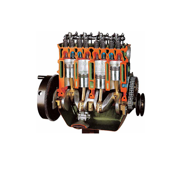
Quick Answer: The Working Model of Valve Timing is a cutaway, multi-cylinder engine model demonstrating valve timing, the precise timing of the opening and closing of the engine's valves, which are usually poppet valves in an internal combustion engine. Professionally painted and sectioned for training purposes with many parts chromium-plated and galvanized for longer life, it shows how valve timing is controlled by the camshaft and can be varied by modifying the camshaft, using variable valve timing, or adjusting the valve mechanism.
The multi-cylinder engine valve timing cutaway model is carefully sectioned for training purposes and professionally painted with different colours to better differentiate the various parts, cross-sections, lubricating circuits, fuel system, and cooling system. Many parts have been chromium-plated and galvanized for a longer life.
In a piston engine, valve timing is the precise timing of the opening and closing of the valves; in an internal combustion engine these are usually poppet valves, while in a steam engine they are usually slide valves or piston valves. In four-stroke cycle engines and some two-stroke cycle engines, valve timing is controlled by the camshaft, and it can be varied by modifying the camshaft or during engine operation by variable valve timing, and is also affected by the adjustment of the valve mechanism.
FEATURES:
MPFI /CRDI engine model ideal for classroom demonstrations.
Measure and draw the valve-timing diagram.
Cross-sectioned various parts to show internal operation.
Operated: Manually
Equipment Layout: On Base with wheel
Fine finish
Simple operations
Functional accuracy
SPECIFICATION:
Fully functional, cut section system is installed in a mobile solid frame.
Sturdy powder coated metal stand consists
4 stroke engine
4 in-line cylinders
Manually operate the mechanism
Indirect injection
Feeding by turbo supercharger
VE Bosch type rotary injection pump
Overhead camshaft (OHC)
Distribution through a toothed belt
DIMENSIONS AND WEIGHT:
L x W x H (approx.): 700 x 700 x 800 mm
Weight (approx.): 65 kg
Contact Engineering Lab Equipment for your School, College Civil and Mechanical Engineering Lab Instruments. We are the best and renowned engineering lab equipments, engineering equipment manufacturer india, engineering equipment india, chemical engineering lab equipments, control engineering laboratory equipments, control engineering laboratory equipment, control engineering lab equipment in Ambala, India.
Last Updated: September 2026
Related Products: Cut Model of Common Rail Turbo Diesel Engine, Cut Section Model of Four Stroke Petrol Engine, Working Model of MPFI Petrol Engine, Working Model of Gear Box