Working Model of Drive Shaft
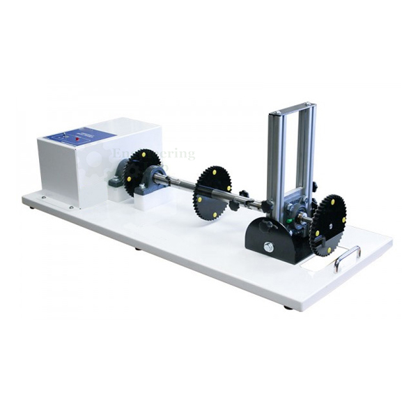
Product Code : EL-AELE-10743
Working Model of Drive Shaft (code EL-AELE-10743) is a demonstration unit for the acceleration and deceleration that occur in universal joints and drive shafts running at an angle, where a constant-speed input shaft drives an output shaft whose speed varies with the angle between them. Driven by an electric motor on a 230 V, 50 Hz single phase supply, it is installed in a mobile frame with adjustable shaft angles, visual indicators and toothed wheels that make the speed changes audible.
Get a quote: use the Add To Cart enquiry button below, or send your quantity and delivery location through the contact page.
Specifications
| Parameter | Detail |
|---|---|
| Use | Demonstrating the acceleration and deceleration in universal joints and drive shafts working at various angles |
| Construction | Fully functional drive shaft system installed in a mobile solid frame |
| Drive | Electric motor |
| Angle adjustment | Universal shaft adjustment; different driveshaft angles selected with the adjustment system |
| Indicators | Visual indicators |
| Audible demonstration | Toothed wheels make the changes in speed audible |
| Power required | 230 V, 50 Hz, single phase |
| Dimensions | Approx. 800 × 500 × 600 mm (L × W × H) |
| Weight | Approx. 45 kg |
| Product code | EL-AELE-10743 |
| Manufacturer | Engineering Lab Equipment, Ambala, Haryana, India |
What Is the Working Model of Drive Shaft Used For?
A universal joint does not pass rotation through at an even rate when its shafts meet at an angle: with the input turning steadily, the output speeds up and slows down during each revolution, and the effect grows as the angle increases, causing vibration and wear over time. Propeller shafts carry drive from the gearbox to the rear axle, and short drive shafts take it from the final drive to the road wheels, so the effect matters on rear- and front-wheel-drive vehicles alike. Students set different shaft angles with the adjustment system, run the motor and compare what the visual indicators show and the toothed wheels sound like at each setting.
What to Specify When Ordering
- Quantity — how many drive shaft models are needed.
Frequently Asked Questions
Why does the output shaft change speed?
When the input and output shafts of a universal joint meet at an angle, the output turns at a varying speed even though the input runs at constant speed, and a larger angle makes the effect greater.
How are the speed changes shown?
Visual indicators show the variation, and toothed wheels make the changes in speed audible, so students can both see and hear the effect.
Can the shaft angle be changed?
Yes, the universal shaft adjustment lets different driveshaft angles be selected, so the effect at small and large angles can be compared.
What power does the model require?
The electric motor runs on a 230 V, 50 Hz, single phase supply, and the whole drive shaft rig sits in a mobile frame of approximately 800 × 500 × 600 mm and 45 kg.
What is the difference between a propeller shaft and a drive shaft?
The propeller shaft transmits power from the gearbox to the rear axle, usually as a tube in one- or two-piece form, while short drive shafts carry drive from the final drive to the road wheels.
OEM Manufacturer
The Working Model of Drive Shaft is made by Engineering Lab Equipment (Engineering Labs Equipment Pvt Ltd) at its works at Plot No. 43, Industrial Park, Sector 2, Growth Center, Saha, District Ambala, Haryana, India. The company designs, makes and tests automobile engineering cut-section models, working models and trainers for engineering colleges, polytechnics, technical training institutes and research laboratories in India and overseas, and can build equipment to an institution's own requirements. Tender and OEM enquiries are handled through the Tenders/OEM page.
Related Automobile Engineering Equipment
- Working Model of Torsion Differential — hand-operated sectioned worm-principle bevel gear differential on a powder coated mobile stand.
- Working Model of Clutch Type Differential — crank-operated sectioned limited slip differential with spring pack and clutch set, light metal construction.
- Cut Model of Rear Axle with Locking Differential — sectioned rear axle with crown and pinion, locking satellite differential, hub reducers and air-operated drum brakes.
- Vehicle Transmission 5 Speed Manual Gearbox — cutaway 4WD transmission with 5 speeds and reverse, 2-speed reduction gear and self-locking hypoid differentials.
See the full Automobile Engineering Lab Equipment range or all Mechanical Engineering Lab Equipment.
Request a Quote
For this and other automobile engineering lab equipment, schools and colleges can contact Engineering Lab Equipment, a manufacturer, supplier and exporter based in Ambala, India. To ask for a quotation, send how many drive shaft models you need and your delivery location through the contact page, or use the Add To Cart enquiry button on this page.
Last updated: October 2026